 |
Check heater cable
insulation integrity using megger as per heater cable manufacturer
recommendations prior to energizing the Local Control Panel.
Energizing
the Local Control Panel
-
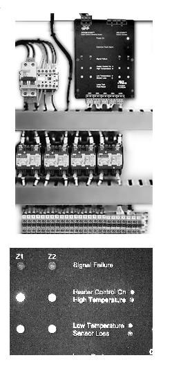
Turn the Control Logic Circuit Breaker on. The
Network Controller and Input / Output Modules (if any) green Power On
Light(s) will illuminate.
- Wait 10 seconds for Network Controller to
initialize.
- Red Signal Failure Lights will illuminate to
indicate no communications between Network Controller and Remote
Terminals.
- Turn, one by one, individual heat tracing cable
circuits breakers on. The Signal Failure Alarms for each zone should
disappear, as the circuit breakers for these zones are turned
on.
- If the system is turned on during extreme cold
weather, amber Low Temperature Lights will illuminate. As the heater
cable warms up the pipe, the Low Temperature Alarm should
disappear.
- The Low Temperature Alarm is doubled with Sensor
Loss (temperature sensor) Alarm. If the temperature sensor is not
connected to the Remote Terminal, Sensor Loss Light will blink
rapidly.
- Green Heater Control On Light is doubled with High Temperature
Alarm (if set at factory per customer specifications). Should the high temperature alarm
set point be reached, the High Temperature Alarm Light will blink
rapidly.
|